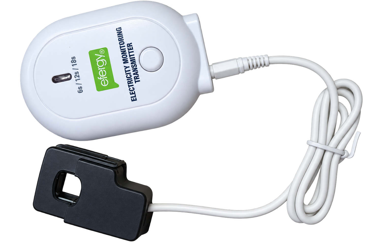
How I decoded an old Efergy transmitter, built a local radio receiver and brought its readings into ESPHome.
My Efergy energy monitor had become disconnected from the online service I used to read it. The CT clamp and battery-powered transmitter were still there, but the useful connection to my home setup had disappeared.
Before replacing the hardware, I wanted to find out whether the transmitter was still sending readings over the air. If it was, perhaps I could receive them myself.
That turned into a project involving a Flipper Zero, a CC1101 radio, a NodeMCU ESP8266 and an ESPHome external component. It now delivers readings locally to Home Assistant.
The hardware was still talking
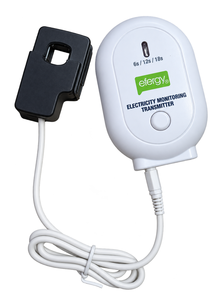
The first distinction is between the clamp and the transmitter. The clamp senses current; the separate battery box measures it and sends the wireless messages.
My transmitter has 6s / 12s / 18s printed on the front. That was a useful clue when looking for an existing decoder.
Efergy lists 433.5 MHz for its Elite/E2/Engage-compatible transmitter family. The rtl_433 E2 Classic decoder documents reception around 433.55 MHz, using FSK modulation and pulse-width encoded data. These provided a starting point, rather than a guarantee that every Efergy variant behaves identically. Efergy specifications, rtl_433 decoder
The arrangement I ended up building is:
Efergy CT clamp
      │
Efergy battery transmitter
      │  433 MHz radio
CC1101 + NodeMCU ESP8266
      │  Wi-Fi / ESPHome native API
Home Assistant
Proving the signal could be decoded
I used a Flipper Zero to record Sub-GHz RAW captures before building the receiver.
Frequency and modulation both mattered. An OOK/AM capture did not give me usable Efergy packets. The standard FSK presets also failed to produce a reliable decode in my tests.
The breakthrough came with a custom CC1101 preset adapted from the 91JJ Efergy ESPHome project. That project targets ESP32; I used its radio configuration as a reference for my ESP8266 implementation.
The useful receiver settings included a roughly 17.3 kbaud modem setting, 270.8 kHz receive bandwidth and 41.3 kHz deviation, with the Flipper tuned to 433.550 MHz. The modem setting is a receiver configuration parameter, not a measurement of the transmitter’s actual data rate.
The successful capture produced 12 distinct checksum-valid packet occurrences. It contained two repeating transmitter IDs: one with a non-zero current reading and another reporting zero. That was a reminder to identify and filter the intended transmitter, rather than accept every nearby reading.
One decoded packet was:
08 4F B8 40 6A DB 02 96Using the E2 Classic interpretation, it gave transmitter ID 47183, or 0xB84F, and a current reading of about 3.339 A. The checksum passed. A plausible number alone would not have been enough evidence; repeated valid packets made the result convincing.
The Flipper was a diagnostic tool for this project. It does not need to remain connected once the ESP receiver is running.
Choosing a board
I had an ESP32-H2 available, but it has no built-in Wi-Fi. I also had a NodeMCU ESP8266, which suited the first Wi-Fi receiver test. An ESP32 is on order, but the working setup described here uses the ESP8266.
The parts are:
- The existing Efergy clamp and battery transmitter.
- A NodeMCU ESP8266 development board.
- A 433 MHz CC1101 module, with an appropriate antenna.
- Jumper wires and USB power.
- Home Assistant with ESPHome Device Builder.
A basic OOK-only 433 MHz receiver is not a substitute for the CC1101 in this build: the decoded Efergy protocol uses FSK.
Wiring the CC1101
These are the connections used by the supplied NodeMCU component. Follow the signal labels on your CC1101 module, because its physical pin arrangement may differ from another module’s.
| CC1101 connection | NodeMCU label | ESP8266 GPIO |
|---|---|---|
| VCC | 3V3 | — |
| GND | GND | — |
| SCK | D5 | 14 |
| MISO / SO | D6 | 12 |
| MOSI / SI | D7 | 13 |
| CSN / CS | D0 | 16 |
| GDO0 | D2 | 4 |
| GDO2 | D1 | 5 |
The radio is powered from 3.3 V. I connected its antenna and kept the jumper wires short.
GDO0 supplies the demodulated data. GDO2 is configured for carrier detection, although the final decoder processes the data continuously rather than gating capture on the carrier signal. GPIO16 is used for chip select; it is not used for an interrupt input.
The frequency mistake that held things up
SPI communication worked straight away: the radio returned its part and version registers. Getting valid packets took more investigation.
The first sketch divided reception into bursts using carrier detection. It overflowed some capture buffers and produced no valid readings. Switching to continuous pulse capture eliminated those overflows, but the decoder still failed.
Then I found a more concrete mistake: the startup message said 433.550 MHz, while the inherited frequency registers actually selected approximately 433.450 MHz.
For a CC1101 with a 26 MHz crystal, the frequency word is calculated as:
frequency word = round(frequency in Hz × 65536 / 26000000)

433550000 Hz → 0x10ACCD
That means the three frequency registers are:
FREQ2 = 0x10
FREQ1 = 0xAC
FREQ0 = 0xCD
Correcting the registers produced live, repeating readings. The radio configuration needed to match the intended frequency, not merely the text printed in the log. The crystal assumption also needs to match the physical module. CC1101 datasheet
Seeing live readings on the ESP8266
Before introducing ESPHome, I tested with an Arduino sketch and USB serial output. Wi-Fi was disabled during this stage so I could check the radio and decoder first.
The working output looked like this:
ID=47183 (0xB84F) current=2.800 A battery=OK interval=6 s checksum=OK seen=5
RAW: 08 4F B8 40 59 99 02 43

ID=47183 (0xB84F) current=2.710 A battery=OK interval=6 s checksum=OK seen=6
RAW: 08 4F B8 40 56 B7 02 5E
The diagnostic counters also showed zero dropped edges and complete 64-bit matching pulse runs.
The receiver timestamps completed high and low periods into a ring buffer. The main loop reconstructs packets, validates the checksum and extracts the current, ID and status fields. Keeping decoding and logging out of the interrupt handler was important for this implementation.
Moving the working receiver into ESPHome
The next step was to package the receiver as a local ESPHome external component. It uses the same decoder and corrected frequency settings, with a filter for my selected transmitter ID.
The project download accompanying this post contains the component, a complete NodeMCU YAML configuration and an example secrets file. The example contains placeholders; readers must supply their own credentials and API key.
On my Home Assistant setup, the relevant files live under the ESPHome configuration directory:
/config/esphome/
├── efergy-receiver.yaml
├── secrets.yaml
└── components/
    └── efergy_receiver/
        ├── __init__.py
        ├── efergy_receiver.h
        ├── efergy_receiver.cpp
        └── EfergyDecoder.h
The local component is loaded with:
external_components:
  - source:
      type: local
      path: components
    components: [efergy_receiver]
The receiver configuration includes:
efergy_receiver:
  transmitter_id: 47183
  mains_voltage: 230.0
  current:
    name: Current
  apparent_power:
    name: Apparent Power
  battery_low:
    name: Transmitter Battery Low
  receiving:
    name: Receiving Transmitter
  packets:
    name: Valid Packets
  dropped_edges:
    name: Dropped Edges
47183 is the ID selected for my setup. Readers should use the ID belonging to their own transmitter. The packaged component has fixed pin assignments matching the wiring table above and currently targets NodeMCU ESP8266.
ESPHome supports loading external components from a local folder, so this component does not require a hosted Git repository. External components documentation
I merged the device’s API and OTA credentials into my existing secrets file, validated the configuration and installed the first ESPHome firmware over USB. Subsequent updates can use ESPHome OTA.
Connecting it to Home Assistant
The device connects over Wi-Fi using ESPHome’s native API. No MQTT broker is involved in this setup.
After flashing, I checked that it was online in Device Builder and inspected the logs. Home Assistant can discover the device, but manual integration is also possible:
- Open Settings → Devices & services → Add integration.
- Select ESPHome.
- Enter the receiver’s IP address, using port 6053.
- Supply the API encryption key if requested.
The resulting entities include current, apparent power, battery-low status, reception status and diagnostic counters.
If the selected transmitter has not supplied a valid packet for 45 seconds, the component marks the current and apparent-power readings unknown and turns off the reception indicator. It does not leave an old consumption reading looking current.
Amps, VA and watts are different measurements
The recovered current reading is useful, but it does not make this a true-power meter.
The component’s apparent-power sensor multiplies current by an assumed voltage:
2.800 A × 230 V = 644 VAThat is apparent power in VA, based on an assumed mains voltage. It is not a measurement of real watts. This setup does not measure voltage or power factor, so I have not exposed its readings as measured watts or kWh for the Home Assistant Energy dashboard.
For this project, bringing the current readings into a local dashboard was already a useful result.
A few troubleshooting lessons
- An upload error is not necessarily a compile error. My Arduino sketch compiled, but an occupied COM port stopped the upload. Closing serial tools and reconnecting USB resolved the next step.
- SPI success does not prove packet reception. Reading the CC1101’s registers confirmed communication, but valid checksums were the meaningful radio test.
- Check actual register values. A convincing frequency label in a log can still be wrong.
- Keep Arduino macros unqualified. The ESPHome port initially used
::noInterrupts()and::interrupts(). Removing::fixed that compiler error on ESP8266. - Check Wi-Fi before discovery. If Home Assistant does not discover the device, first check that ESPHome shows it online, then add it by IP if needed.
A working local connection
The Efergy clamp and transmitter now have a useful connection again. The new receiver listens to the existing radio messages and sends the decoded readings directly into Home Assistant.
This was possible because of the groundwork in rtl_433 and the 91JJ Efergy project. The work here was adapting those references to an ESP8266, verifying the signal, correcting the tuning and integrating the successful decoder with ESPHome.
My next hardware experiment will be moving the receiver to the ESP32 I have ordered. For now, the NodeMCU is already doing the job.
Leave a Reply